File Systems and I/O - Modern Operating System
Files
File Types
executable file
Example:
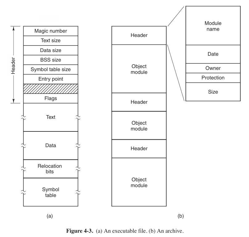
.exein Windows.An executive files has five sections: header, text, data, relocation bits, and symbol table.
The header starts with a so-called magic number, identifying the file as an executable file (to prevent the accidental execution of a file not in this format). Then come the sizes of the various pieces of the file, the address at which execution starts, and some flag bits.
Following the header are the text and data of the program itself. These are loaded into memory and relocated using the relocation bits. The symbol table is used for debugging.
archive (归档文件)
Example:
.zip,.tar,.rarIt consists of a collection of library procedures (modules) compiled but not linked. Each one begins with a header telling its name, creation date, owner, protection code, and size. Just as with the executable file, the module headers are full of binary numbers. Copying them to the printer would produce complete mess.
An Example Program Using File-System Calls
Here is an instance that how we use file-system calls
1 | |
Why there must be 3 parameters in argv? Because each argv has its meaning.
argv[0]is the name of this program, which is bound in C language program.argv[1]is the path of input file.argv[2]is the path of output file.
For instance, this program, named copyfile, executes by the command line
1 | |
then it copies the file abc to xyz.
Directories
Path Names
Different operating systems have different path names.
Windows:
\usr\ast\mailboxUNIX:
/usr/ast/mailboxMULTICS:
>usr>ast>mailbox
Be attention to distinguish the difference of relative path name and absolute path name
Directory Operations
Here we mainly focus on the operation Link and Unlink.
Link. Linking is a technique that allows a file to appear in more than one directory. This call can create a hard link.
Unlink. A directory entry is removed.
A variant on the idea of linking files is the symbolic link. Instead, of having two names point to the same internal data structure representing a file, a name can be created that points to a tiny file naming another file.
File-System Implementation
File System Layout
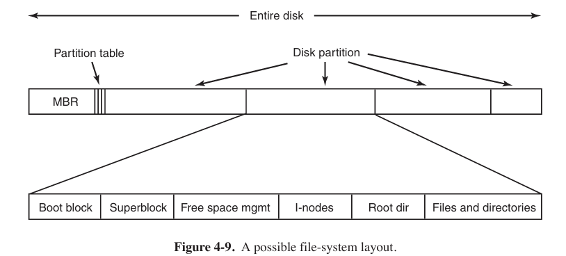
File systems are stored on disks. Most disks can be divided up into one or more partitions, with independent file systems on each partition. Sector 0 of the disk is called the MBR (Master Boot Record) and is used to boot the computer. The end of the MBR contains the partition table. This table gives the starting and ending addresses of each partition. One of the partitions in the table is marked as active. When the computer is booted, the BIOS reads in and executes the MBR.
Other than starting with a boot block, the layout of a disk partition varies a lot from file system to file system. Often the file system will contain some of the items. The first one is the superblock. This block contains global information and key parameters of whole file system.
The MBR is the Sector 0 of whole disk and used to guide BIOS and portion table, not being any part of certain file system. While super block is the beginning position of certain file system. But usually, a portion of disk maps a file system.
Implementing Files
- Contiguous Allocation (连续分配)
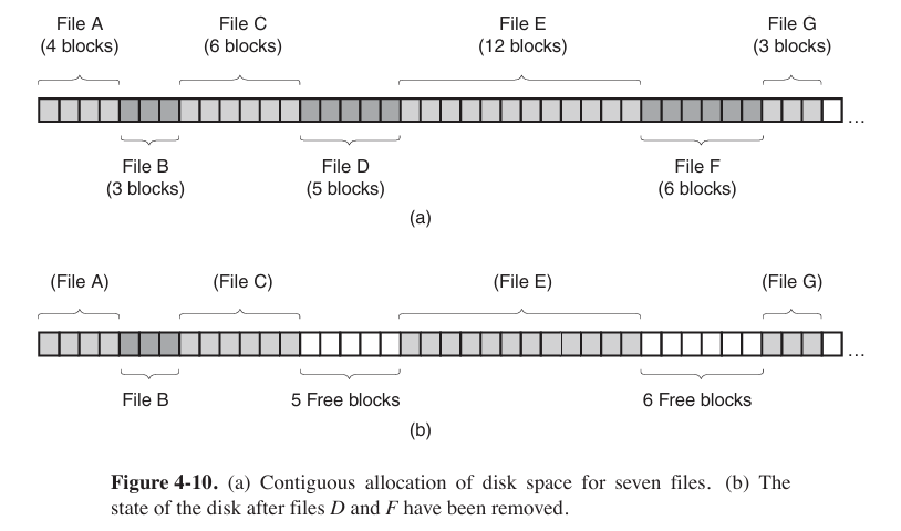
This method has two advantages. First, it is simple to implement. Second, the read performance is excellent (because the entire file can be read from the disk in a single operation).
However, contiguous allocation also has a very serious drawback: over the course of time, the disk becomes fragmented (碎片化).
- Linked-List Allocation
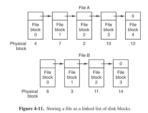
Now no space is lost to disk fragmentation. On the other hand, although reading a file sequentially is straightforward, random access is extremely slow.
Also, the amount of data storage in a block is no longer a power of two (2的幂) because the pointer takes up a few bytes.
- Linked-List Allocation Using a Table in Memory
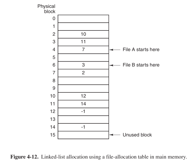
In Fig. 4-11 and Fig. 4-12, we have two files. File A uses disk blocks 4, 7, 2, 10, and 12, in that order, and file B uses disk blocks 6, 3, 11, and 14, in that order. Using the table of Fig. 4-12, we can start with block 4 and follow the chain all the way to the end. The same can be done starting with block 6. Both chains are terminated with a special marker (e.g., −1) that is not a valid block number. Such a table in main memory is called a FAT (File Allocation Table).
Using this organization, the entire block is available for data. Furthermore, random access is much easier.
The primary disadvantage of this method is that the entire table must be in memory all the time to make it work. Clearly the FAT idea does not scale well to large disks.
It was the original MS-DOS file system and is still fully supported by early versions of Windows though.
- I-nodes
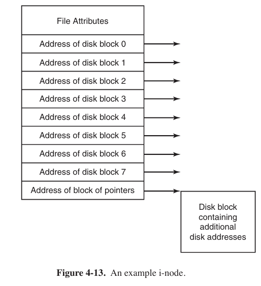
Associating with each file a data structure called an i-node (index-node), which lists the attributes and disk addresses of the file’s blocks.
The big advantage of this scheme over linked files using an in-memory table is that the i-node need be in memory only when the corresponding file is open.
It is often used in Linux/Unix file system (Ext 2/3/4) and Windows (NTFS).
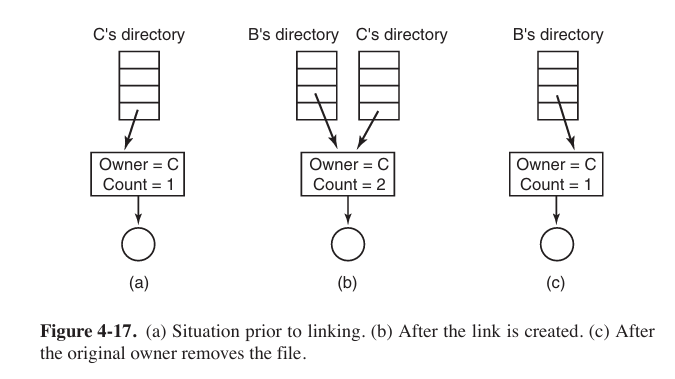
Share Files
In UNIX there are two ways to share files: symbolic linking and hard linking. Assume that there are two files: B and C.
symbolic link
Use
ln -s [source file or directory] [symbolic name]command to create a symbolic link.Essentially symbolic link is just a special file that points to another file or directory.
B links to C by having the system create a new file, of type LINK. The new file contains just just the path name of the file to which it is linked. When B reads from the linked file, the operating system sees that the file being read from is of type LINK, looks up the name of the file, and reads that file.
Symbolic name can be used when you wanna access file from other directory (say, Desktop).
Even the symbolic link itself is a file, so when creating it, an i-node is created.
hard link
Use
ln [source file] [hard link name]command to create a hard link.Essentially hard link is just different entry of a file.
Disk blocks are not listed in directories, but in a little data structure associated with the file itself. The directories would then point just to the little data structure (or i-node in UNIX).
Hard link can be used when you want a file has multiple name and do not wanna lose file because of deleting one name.
Log-Structure File Systems
The LFS (Log-Structure File System) sees all changes on file system as a journal records, and appends the records on s constant region of disks in order.
Journaling File System
It is a tradition file system that appends a journal record, mainly recording changes in data.
File-System Backups
Tw o strategies can be used for dumping a disk to a backup disk: a physical dump or a logical dump.
A physical dump starts at block 0 of the disk, writes all the disk blocks onto the output disk in order, and stops when it has copied the last one. Such a program is so simple that it can probably be made 100% bug free. The main advantages of physical dumping are simplicity and great speed (basically, it can run at the speed of the disk). The main disadvantages are the inability to skip selected directories, make incremental dumps, and restore individual files upon request.
A logical dump starts at one or more specified directories and recursively dumps all files and directories found there that have changed since some given base date (e.g., the last backup for an incremental dump or system installation for a full dump).
The UNIX V7 File System
The file system is in the form of a tree starting at the root directory, with the addition of links. forming acyclic graph (无环图).
A UNIX directory entry contains one entry for each file. The entries is simple because UNIX uses the i-node scheme. A directory contains only two fields: the file name and the number of the i-node for that file.
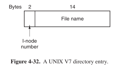
Because I-node number takes up to 2 bytes, 16 bits, so quantity of files is $2^{16}$. But file name quantity might be bigger than $2^{16}$ since hard link’s existence.
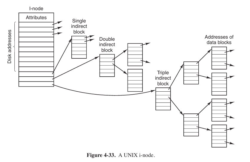
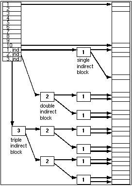
Keeping track of disk blocks is done using a generalization of Fig. 4-13 in order to handle very large files. The first 10 disk addresses are stored in the i-node itself, so for small files, all the necessary information is right in the i-node. For somewhat larger files, one of the addresses in the i-node is the address of a disk block called a single indirect block. This block contains additional disk addresses. If this still is not enough, another address in the i-node, called a double indirect block, contains the address of a block that contains a list of single indirect blocks. Each of these single indirect blocks points to a few hundred data blocks. If even this is not enough, a triple indirect block can also be used.
I/O
Principles of I/O Hardware
I/O Device
I/O devices can be roughly divided into two categories: block devices and character devices.
A block device is one that stores information in fixed-size blocks, each one with its own address. The essential property of a block device is that it is possible to read or write each block independently of all the other ones. Hard disks, Blu-ray discs, and USB sticks are common block devices.
A character device delivers or accepts a stream of characters, without regard to any block structure. It is not addressable and does not have any seek operation. Printers, network interfaces, mice, and most other devices that are not disk-like can be seen as character devices.
Memory-Mapped I/O
Early operating systems (like Intel 8086 or some embedded OS) use separate I/O, which means we need a separate bus to execute these commands, while concurrent access (并发访问) is hardly possible. CPU must use special commands (say in and out) to communicate with devices. But now we often map memory address with I/O devices’ registers or something else.
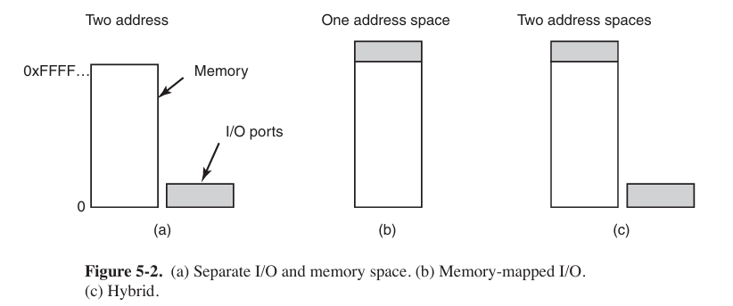
Each controller has a few registers that are used for communicating with the CPU. In addition to the control registers, many devices have a data buffer that the operating system can read and write. The issue thus arises of how the CPU communicates with the control registers and also with the device data buffers. Two alternatives exist.
In the first approach, each control register is assigned an I/O port number. The set of all the I/O ports form the I/O port space, which is protected so that ordinary user programs cannot access it (only the operating system can).
The second approach is to map all the control registers into the memory space. Each control register is assigned a unique memory address to which no memory is assigned. This system is called memory-mapped I/O. The x86 uses the hybrid scheme.
Direct Memory Access
No matter whether a CPU does or does not have memory-mapped I/O, it needs to address the device controllers to exchange data with them. The CPU can request data from an I/O controller one byte at a time, but doing so wastes the CPU’s time, so a different scheme, called DMA (Direct Memory Access) is often used.
Then the DMA takes change of bus.
Let us first look at how disk reads occur when DMA is not used.
- the disk controller reads the block (one or more sectors) from the drive serially, bit by bit, until the entire block is in the controller’s internal buffer.
- it computes the checksum to verify that no read errors have occurred.
- the controller causes an interrupt.
When the operating system starts running, it can read the disk block from the controller’s buffer a byte or a word at a time by executing a loop, with each iteration reading one byte or word from a controller device register and storing it in main memory.
When DMA is used, the procedure is different.
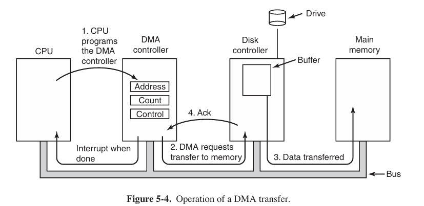
- the CPU programs the DMA controller by setting its registers so it knows what to transfer where. It also issues a command to the disk controller telling it to read data from the disk into its internal buffer and verify the checksum. When valid data are in the disk controller’s buffer, DMA can begin.
- The DMA controller initiates the transfer by issuing a read request over the bus to the disk controller.
- When the disk controller fetches the next word from its internal buffer, it knows where to write it. The write to memory is another standard bus cycle.
- When the write is complete, the disk controller sends an acknowledgement signal to the DMA controller, also over the bus.
But not all computers use DMA. The argument against it is that the main CPU is often far faster than the DMA controller and can do the job much faster. If there is no other work for it to do, having the (fast) CPU wait for the (slow) DMA controller to finish is pointless. Also, getting rid of the DMA controller and having the CPU do all the work in software saves money, important on low-end (embedded) computers.
Interrupts Revisited
Interrupts can be categorized by 2 types: precise interrupt and imprecise interrupt. A precise interrupt leaves the machine in a well-defined state. Such an interrupt has four properties:
- The PC (program counter) is saved in a known place.
- All instructions before the one pointed by the PC (由程序计数器指向的) have completed.
- No instruction beyond the one pointed to by the PC has finished.
- The execution state os the instruction pointed by the PC is known.
An interrupt that does not meet these requirements is called an imprecise interrupt.
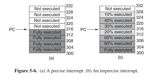
Some machines, such as the x86 family, hav e precise interrupts to allow old software to work correctly.
Principles of I/O Software
Programmed I/O
The simplest form of I/O is to have CPU do all work. This method is called programmed I/O. This is simple but has the disadvantage of typing up the CPU full time until all the I/O is done.
Interrupt-Driven I/O
When the system call, for example, to print the string is made, the buffer is copied to kernel space, as we showed earlier, and the first character is copied to the printer as soon as it is willing to accept a character. At that point the CPU calls the scheduler and some other process is run. The process that asked for the string to be printed is blocked until the entire string has printed. When the printer has printed the character and is prepared to accept the next one, it generates an interrupt. This interrupt stops the current process and saves its state. Then the printer interrupt-service procedure is run.
An obvious disadvantage of interrupt-driven I/O is that an interrupt occurs on ev ery character. Interrupts take time, so this scheme wastes a certain amount of CPU time.
Using DMA
A solution is to use DMA. Here the idea is to let the DMA controller feed the characters to the printer one at time, without the CPU being bothered.
The big win with DMA is reducing the number of interrupts from one per character to one per buffer printed. If there are many characters and interrupts are slow, this can be a major improvement. On the other hand, the DMA controller is usually much slower than the main CPU. If the DMA controller is not capable of driving the device at full speed, or the CPU usually has nothing to do anyway while waiting for the DMA interrupt, then interrupt-driven I/O or even programmed I/O may be better. Most of the time, though, DMA is worth it.
Disk Formatting
Before the disk can be used, each platter (磁盘片) must receive a low-level format done by software.
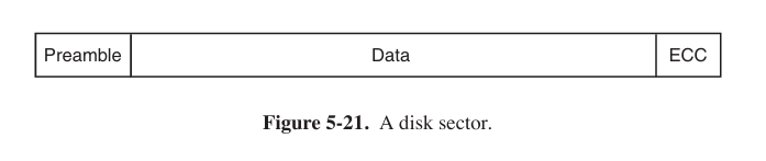
The preamble starts with a certain bit pattern that allows the hardware to recognize the start of the sector. The ECC field contains redundant (冗余) information that can be used to recover from read errors.
The position of sector 0 on each track is offset from the previous track when the low-level format is laid down. This offset, called cylinder skew (柱面斜进), is done to improve performance. The idea is to allow the disk to read multiple tracks in one continuous operation without losing data.
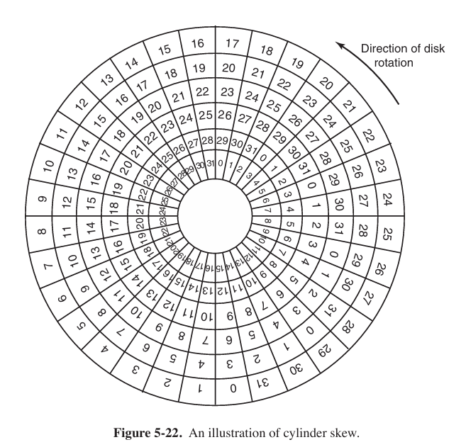
As a result of the low-level formatting, disk capacity is reduced.
The final step in preparing a disk for use is to perform a high-level format of each partition (separately). This operation lays down a boot block, the free storage administration (free list or bitmap), root directory, and an empty file system.
low-level format initializes sectors, high-level skew format initialize boot blocks and data structure that manages free blocks.
User Interfaces: Fonts
In versions of Windows before 3.1, characters were represented as bitmaps. But it cannot change point type. The solution was the introduction od TrueType fonts. Each TrueType character is defined by a sequence of points around its perimeter (边缘). Using this system, it is easy to scale the characters up or down. All that has to be done is to multiply each coordinate (坐标) by the same scale factor. Once at the proper size, the points can be connected using the follow-the-dots algorithm.
Power Management of CPU

On many computers, there is a relationship between CPU voltage, clock cycle, and power usage. The CPU voltage can often be reduced in software, which saves energy but also reduces the clock cycle (approximately linearly). Since power consumed is proportional to the square of the voltage, cutting the voltage in half makes the CPU about half as fast but at 1/4 the power.